
Click the link below to view all schematics as a PDF.
TIVA Microcontroller Pin Assignments

The pins on the TIVA were assigned in a way to maximize grouping pins required for the same subsystems, while following certain constraints. Some pins could only be used for certain alternate functions, such as PWM lines, wide timers, and interrupts, and so they were assigned accordingly. These pins include those used for the motor PWMs, encoder input captures, and color sensor, SPUD, and accelerometer serial communications.
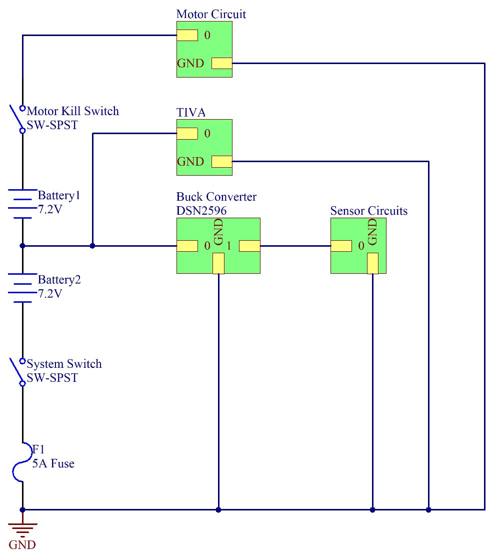
Power Distribution
|
Power to the robot was supplied using two 7.2V NiMH batteries. Due to the differing requirements of the power circuits and sensors in the robot, power was routed through a terminal block which connected the batteries and provided a common ground. The first battery supplies 7.2V to the TIVA, which in turn regulates the voltage into 5V and 3.3V. The 3.3V is used for the SPUD and the accelerometer. The 7.2V line is also passed through a buck converter to create a 5V line that is used to power all logic and sensor circuits in the robot. A second battery connected in series allows 14.4V to be supplied to the motor drivers.
Two kill switches are used in power distribution: a total system switch to power the robot on and off, and a separate kill switch for the motor circuits. A 5A fuse is used in series with the first battery to provide overcurrent protection. |
Motor Drive

The motor drive train is powered by two TLE-5206-2 motor drivers, each equipped with 0.1uF and 470uF capacitors. The drivers were controlled by 2 PWM lines (PB6 and PB7) from the TIVA, as well as two digital, direction lines (PB4 and PB5). The direction and PWM lines are flipped in the right motor compared to the left, as the motors are oriented in opposite directions.
Closed-loop, PID control was implemented using encoders mounted on the motor shafts. The encoders are supplied by 5V, and the encoder ticks are recorded through input capture interrupts in PC4 and PC5.
Closed-loop, PID control was implemented using encoders mounted on the motor shafts. The encoders are supplied by 5V, and the encoder ticks are recorded through input capture interrupts in PC4 and PC5.
IR Detection
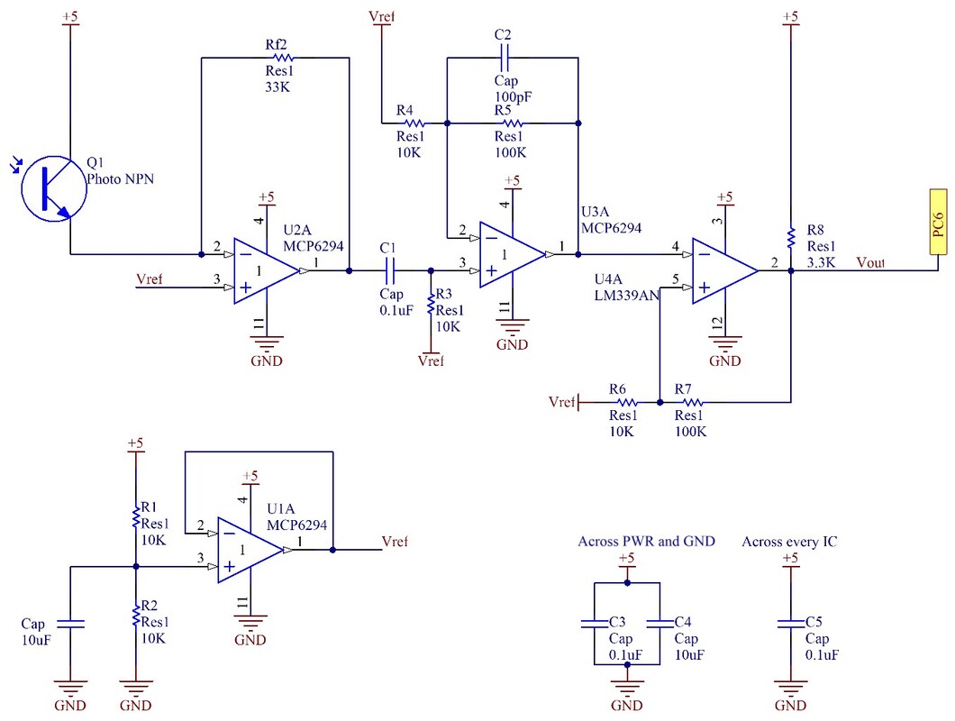
Infrared pulses are detected using a 3-stage circuit, comprised of a transresistive stage, a gain stage, and a comparator with hysteresis to generate a clean digital output signal to the TIVA. A 2.5 reference voltage was created using a voltage divider and a unity buffer. The circuit is able to capture IR pulses from up to 10 feet away. The period of the pulses are computed by input capture interrupts in the microcontroller.
SPUD Communication

|
The TIVA communicates with the SPUD through SPI, using the PA2, PA3, PA4, and PA5 pins. At a rate of 500Hz, the TIVA outputs on the read register the address of the SPUD register to be read. After each read/write, there is a 2ms buffer before the next operation is done. This operation is done for each of the 11 registers on the SPUD, in sequence.
|
Accelerometer

|
Similar to the SPUD, the accelerometer interfaces with the TIVA through SPI communication. In sequence, the TIVA queries the X, Y, and Z force readings from the sensor. Each cycle of reads requires 7 query operations.
|
Color Sensor

|
The TIVA communicates with the color sensor through I2C protocol.
|
Beam Break

|
The beam break sensor is powered by 5V on the emitter and receiver sides. When the IR beam is uninterrupted, the receiver outputs a logic high to PC7, and a logic low when the beam is broken. An internal pull up resistor is configured for PC7 to pull the output up to a logic high.
|
Electromagnet

|
The robot uses a 5V, 25kg electromagnet to hold and transport the MINER in the competition. A large magnet was deemed necessary for a reliable mechanism. Due to the relatively high current draw (0.6A), a N-channel power MOSFET is used to switch the magnet on and off with logic from PE5 at the gate. The MOSFET also has a built-in Zener diode to protect against inductive kickback.
|
Limit Switches

Three limit switches are used on the robot to detect collisions in the front and the rear bumpers. In the default position, the output is pulled high through a 10K resistor. When the switch is pressed during a collision, the output is pulled to ground and registers as a logic low.
LEDs
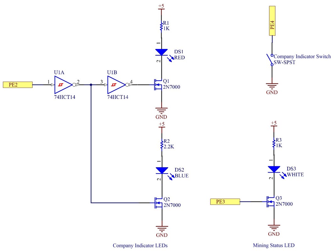
Red and blue diffused gumdrop LEDs are used to indicator the team or company of the robot, while a similar, white LED is used to indicate status of mining operations. The team LEDs are switched on and off by output from PE2, which is passed through an inverter to reach the gate of a N-channel MOSFET. The signal is inverted again to switch the red LED, so that only one of red or blue is on at a time. The clear LED is switched in the same way.
A toggle switch is used to select the team/company of the robot. The switch connects to PE4 on the TIVA in series, and it is pulled high using the TIVA pin's internal pull up resistor.
A toggle switch is used to select the team/company of the robot. The switch connects to PE4 on the TIVA in series, and it is pulled high using the TIVA pin's internal pull up resistor.
