
Electrical Block Diagram
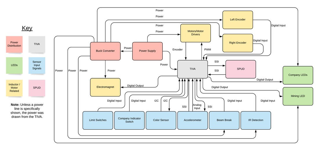
The robotic system was composed of sixteen major components, each designated with its own block in the diagram above. The TIVA (gray block) was the micro-controller utilized to control the robot. The TIVA received sensory input signals from limit switches, company indictor switch, color sensor, accelerometer, beam break, and IR detection circuit (blue blocks). The SPUD (pink block) provided SSI communication to the TIVA. The TIVA received its power directly from the power supply (red block). Inductive/motor related components (yellow blocks) were controlled via TIVA output. LEDs were also controlled via TIVA output (green blocks). The battery power voltage was converted to 5V via a buck convert (red block) which powered many of the smaller circuits. Unless a power line is specifically shown, the power was drawn from the TIVA.
